
If, now, the apparatus be revolved through 90° so that the second pencil is brought into the direction of the earth’s motion, its path will have lengthenedwave-lengths. The total change in the position of the interference bands would be
of the distance between the bands, a quantit}r easily measurable.
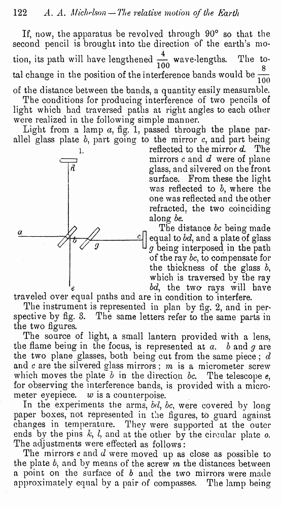
The conditions for producing interference of two pencils of light which had traversed paths at right angles to each other were realized in the following simple manner.
Light from a lamp a) fig. 1, passed through the plane parallel glass plate 5, part going to the mirror c, and part being-
reflected to the mirror d. The mirrors c and d were of plane glass, and silvered on the front surface. From these the light was reflected to b, where the one was reflected and the other refracted, the two coinciding along be.
The distance be being made equal to bd, and a plate of glass g being interposed in the path of the ray be, to compensate for the thickness of the glass b, which is traversed by the ray bd, the two* rays will have traveled over equal paths and are in condition to interfere.
The instrument is represented in plan by fig. 2, and in perspective by fig. 3. The same letters refer to the same parts in the two figures.
The source of light, a small lantern provided with a lens, the flame being in the focus, is represented at a. b and g are the two plane glasses, both being cut from the same piece ; d and c are the silvered glass mirrors ; m is a micrometer screw which moves the plate b in the direction be. The telescope e, for observing the interference bands, is provided with a micrometer eyepiece, w is a counterpoise.
In the experiments the arms, bd) be, were covered by long paper boxes, not represented in the figures, to guard against changes in temperature. They were supported at the '"outer ends by the pins h, I, and at the other by the circular plate o. The adjustments were effected as follows:
The mirrors c and d were moved up as close as possible to the plate 6, and by means of the screw m the distances between a point on the surface of b and the two mirrors were made approximately equal by a pair of compasses. The lamp being
lit, a small hole made in a screen placed before it served as a point of light; and the plate 5, which was adjustable in two planes, was moved about till the two images of the point of light, which were reflected by the mirrors, coincided. Then a sodium flame placed at a produced at once the interference bands. These could then be altered in width, position, or direction, by a slight movement of the plate b, and when they were of convenient width and of maximum sharpness, the
sodium flame was removed and the lamp again substituted. The screw m was then slowly turned till the bands reappeared. They were then of course colored, except the central band, which was nearly black. The observing telescope had to be focussed on the surface of the mirror c/, where the fringes were most distinct. The whole apparatus, including the lamp and the telescope, was movable about a vertical axis.
It will be observed that this apparatus can very easily be