
branch again into two; the two pairs being joined each to one of the tubes. The branches were provided with large valves, by turning which the current was made to flow in either direction through the tubes and into a large tank, from which it was afterward pumped up to the upper tank again. The flow lasted about three minutes, which gave time for a number of observations, with the flow in alternating directions.
Method of observation.—In the first series of observations a single wire micrometer was used in the eyepiece of the observing telescope, but afterward a double wire micrometer was employed. The tubes being filled with distilled water, the light from an electric lamp was directed toward the central glass of the refractometer and the latter adjusted by screws till the light passed centrally down both tubes, and then the right angled prism at the further end adjusted till the light returned and was reflected into the telescope, where generally two images were observed. These were made to coincide, and the fringes at once appeared. They could then be altered in width or direction by the screws, till the best result was obtained. A slight motion of one of the mirrors produced an inclination of the fringes, and the horizontal wire of the micrometer was placed at the portion of the fringes which remained fixed, notwithstanding the movement of the mirror. This adjustment was frequently verified, and as long as it was true, no motion of the tubes or distortion of the glasses could have any effect on the measurements. During this adjustment it was found convenient to have a slow current of water, to avoid distortions on account of unequal density.
The signal being given the current was turned on, and the micrometer lines set, one on each of the two dark bands on either side of the central bright fringe, and the readings noted. The difference between them gave the width of the fringe, and their mean, the position of the center of the central white fringe. This being verified the signal was given to reverse the current ; when the fringes were displaced, and the same measurements taken ; and this was continued till the water was all out of the upper tank. Following is a specimen of one such set of observations.
No. 63.
Direction of current, Micrometer wire,
I
II 13 10
13
14 10
+
r.
I.
80
71
7#
67
65
61
r.
34
35 40 38 40 35
93 88 90 92 89
94
Means
11*8 37-0
69'5 91*0
Width of fringe - _.
Mean width.......
Displacement_____
Mean displacement
48*8
60*5
54*6 +(3-0=index error) 46*0
51-8
(Long tube, vertical fringes, full current.)
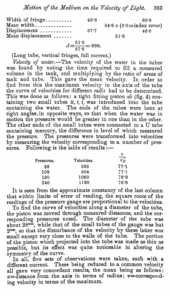
Velocity of water.—The velocity of the water in the tubes was found by noting the time required to fill a measured volume in the tank, and multiplying by the ratio of areas of tank and tube. This gave the mean velocity. In order to find from this the maximum velocity in the axis of the tube the curve of velocities for different radii had to be determined. This was done as follows: a tight fitting piston db (fig. 4) containing two small tubes W, t, t, was introduced into the tube containing the water. The ends of the tubes were bent at right angles, in opposite ways, so that when the water was in motion the pressure would be greater in one than in the other. The other ends of the small tubes were connected to a U tube containing mercury, the difference in level of which measured the pressure. The pressures were transformed into velocities by measuring the velocity corresponding to a number of pressures. Following is the table of results :—
It is seen from the approximate constancy of the last column that within limits of error of reading, the square roots of the readings of the pressure gauge are proportional to the velocities.
To find the curve of velocities along a diameter of the tube, the piston was moved through measured distances, and the corresponding pressures noted. The diameter of the tube was about 28mm, while that of the small tubes of the gauge was but 2mm, so that the disturbance of the velocity by these latter was small except very close to the walls of the tube. The portion of the piston which projected into the tube was made as thin as possible, but its effect was quite noticeable in altering the symmetry of the curve.
In all, five sets of observations were taken, each with a different current. These being reduced to a common velocity all gave very concordant results, the mean being as follows: x= distance from the axis in terms of radius; v=correspond-ing velocity in terms of the maximum.
V
Pressures.
26
108
190
240
Velocities.
393
804
1060
1190
Vp
77*1
TV'l
76*9
76-8