ether. We wish to calculate the transit times of a light ray in each arm in the moving system. The length of arm 1 in Fig. 1 is contracted by the Lorentz contraction:
where c is the vacuum velocity of light. The velocity of light in this arm is
Here we used eq. (2); the (+ ) sign referring to the velocity parallel to v while (—) to the velocity antiparallel to v.
During the light transit, mirror Mx and beam splitter B move to the right, so that the light travels distances
where t± refers to the respective transit times in the two directions. Multiplication of eq. (4) by t± yields the distance Z±. We thus obtain
(t is the transit time of the light from B to M2).
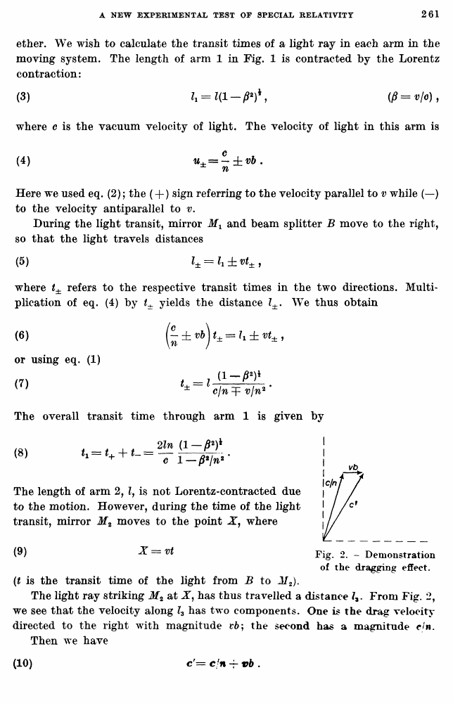
The light ray striking M2 at X, has thus travelled a distance From Fig. 2, we see that the velocity along l3 has two components. One is the drag velocity directed to the right with magnitude t*6; the second has a magnitude cjn. Then we have
(3)
W
(5)
(6)
or using eq. (1) (7)
The overall transit time through arm 1 is given by
(8)
The length of arm 2, lf is not Lorentz-contracted due to the motion. However, during the time of the light transit, mirror M2 moves to the point X, where
(9)
X=vt
Fig. 2. - Demonstration of the dragging effect.
(10)
c'= c/n vb .
Multiplying this equation by t we obtain the relation between the distances Z2, h and (x — y) that appear in Fig. 1:
(11)
Using eq. (1), we can express y by (12)
Again, from Fig. 1
or
(13)
We obtain then that the overall transit time through arm 2 is
(14)
The difference in transit times between the two arms is given by
(15)
Expanding and retaining only terms of second order in /? we have
(16)
If the frequency of light is v and its wave length in vacuum A, the phase difference of the two beams will be
(17)
A rotation of 90° will interchange arms 1 and 2, but will not affect the frequency v of the light source [a laser] due to our assumption that the MME gives a negative result in vacuum. We thus have for the total observed fringe shift for a 90° rotation of the system,
(IB)
3. - The experimental system.
The Michelson-interferometer arms consisted of perspex rods, and the light source was a He-Ne laser. For sensitive detection of fringe shifts, the fringes